Popular Searches
Under a given mill output condition, adjustable orifices are used to balance the airflow velocity of each coal pipe and then locked. However, once the mill output changes (i.e. the airflow varies), the flow velocity in each coal pipe drifts out of balance again.
The root cause is that the total resistance coefficient of each coal pipe is not a constant; the way they vary with Reynolds number and pulverized-coal concentration differs from pipe to pipe. An adjustable orifice can only achieve resistance matching at a single operating point and cannot make the resistance curves coincide across the full range of operating conditions.
The analysis below is broken down layer by layer, in the light of the earlier pipeline model and the characteristics of industrial coal-powder pipelines.
1.Ideal Single-Phase Clear-Water Pipeline
For single-phase clear water in fully developed turbulent flow, or for pure air:
Pipeline head loss: 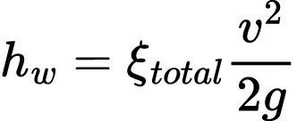 ,
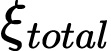 total is treated as a constant.
As long as the valves/orifices are adjusted so that the total resistance coefficients of all pipelines are equal, the flow velocity will be equal at any flow rate.
Premise of this model: single-phase fluid; the resistance coefficient ξ of all components does not change with Reynolds number Re.
A coal-powder pipeline does not carry single-phase air; it carries gas-solid two-phase flow, and the resistance composition of each pipeline differs. This is the essential difference.
2. Resistance Composition of Coal Pipes for Medium-Speed Mills
ξ_total = ξ_pipeline + ξ_adjustable orifice
ξ_pipeline includes distributors, straight pipes, elbows, reducers, pulverized-coal turning sections and burner inlets. Because the spatial routing from the mill to the burners differs, the number of elbows, pipe lengths, turning angles and local vortex structures differ; the resistance of each pipe body has distinct variation characteristics with Re and pulverized-coal concentration.
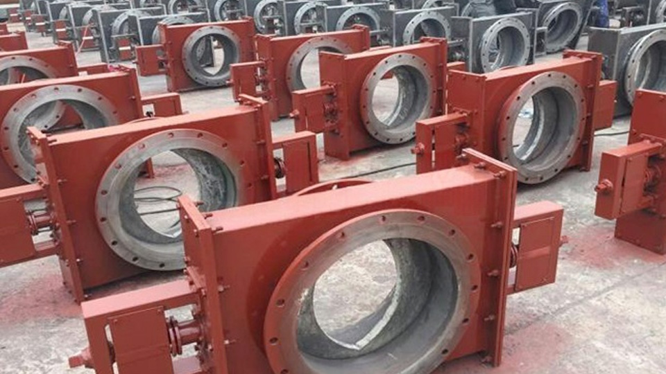
ξ_adjustable orifice provides static compensation to make up the resistance difference under the calibrated output condition. Once the orifice is locked, its geometry is fixed.
Function of the adjustable orifice: single-point matching. Under the calibrated output and calibrated pulverized-coal concentration, the throttling resistance of the orifice is adjusted to pull the total resistance of the whole pipeline set into line, at which point the airflow velocity of each pipe is equal. However, the orifice can only compensate the resistance difference under the calibrated condition; it cannot compensate the difference in the way resistance varies with flow rate / pulverized-coal concentration.
3. Velocity Deviation Occurs Once the Mill Output Changes
3.1 Gas-solid two-phase flow resistance: strong correlation between the resistance coefficient and pulverized-coal concentration & flow velocity (the core factor)
The coal pipe carries two-phase flow of air plus pulverized-coal particles. The total pressure loss of two-phase flow = the single-phase resistance of air + the additional particle-induced resistance.
The additional particle-induced resistance is not a simple v² relationship; it is closely related to the pulverized-coal concentration (gas-solid ratio), particle settling, wall deposition, and particle impingement/wear on elbows.
A rise in mill output → higher mass flow rate of pulverized coal → larger gas-solid ratio;
For the pipe with more elbows and longer length, the additional particle-induced resistance rises more markedly with the gas-solid ratio;
For the pipe with fewer elbows and shorter length, the additional particle-induced resistance rises more mildly with the gas-solid ratio.
A total resistance that has just been balanced at a given air-coal ratio will break balance once the operating condition of the medium-speed mill changes, because the resistance increments of the pipelines differ.
Single-phase air: the resistance of all pipelines scales up proportionally with v². Two-phase pulverized-coal flow: the amplification factor of each pipeline resistance with output differs from pipe to pipe.
3.2 Variation differences of the single-phase resistance coefficient with Reynolds number
Even without considering pulverized coal, looking only at the air:
Long pipe with many elbows: friction resistance dominates; the friction resistance coefficient λ varies with Re in the transition region;
Short pipe with few elbows: local resistance dominates; the local resistance coefficient varies relatively gently with Re.
When the airflow drops and Re decreases: the attenuation law of the pipe-body resistance ≠ the attenuation law of the orifice throttling resistance. Therefore, the total resistance coefficients that were originally matched are no longer equal at low Re.
An adjustable orifice is a local throttling element. The way its throttling resistance coefficient varies with Re differs from that of elbows and straight pipes.
3.3 Resistance drift caused by pulverized-coal deposition and ash accumulation
Pipelines with different routings have different gravitational settling characteristics:
Downward-bending and long horizontal pipes: more prone to pulverized-coal deposition at low velocity; ash deposits reduce the effective flow cross-section and cause a non-linear rise in pipeline resistance;
Upward-inclined pipes: relatively less deposition.
At low mill output, the in-pipe velocity drops and the deposition differences are amplified, further widening the resistance gap between pipes. When the output rises, the high velocity blows the accumulated ash away and the resistance changes again. The degree of ash accumulation in each pipe varies with the operating condition — this is a typical non-linear disturbance that single-point balancing cannot solve.
3.4 The pressure distribution in the mill outlet distribution chamber is not an ideal constant-pressure source
In the earlier vessel model, the vessel has a large volume and all outlets share the same static pressure head H. The outlet of a medium-speed mill is not an ideal pressure-stabilized chamber:
Inside the pulverized-coal distribution box / separator outlet of the mill, there is swirl and biased flow; the static pressure at the tapping position of each coal pipe itself varies with the total mill airflow and output. Under the calibrated output, the flow field in the distribution box is stable and the inlet static pressures of the pipes are close; when the mill output changes substantially, the rotating flow field inside the separator changes and the inlet static pressures of the four / six coal pipes are no longer consistent.
In other words, the pipelines no longer share the same driving pressure; even if the pipeline resistances are equal, the flow velocities will differ.
4. Comparison: Single-Phase Clear-Water Pipeline vs. Pulverized-Coal Pipeline
4.1 Single-phase clear water (ideal)

Adjust the orifices so that K1 = K2; the flow velocities are then equal at any flow rate, and the two resistance curves coincide completely.
4.2 Pulverized-coal two-phase pipeline
 Both K1 and K2 are functions of the flow velocity v and the air-coal ratio μ, and the functional forms of the two pipelines differ. Equality ΔP1 = ΔP2 can only be achieved at a single point ; once v or μ changes, K1 and K2 change by different amounts, giving ΔP1 ≠ ΔP2 and velocity imbalance.
Intuitive understanding: single-phase pipeline — the two resistance curves can be adjusted to coincide completely; coal-powder pipeline — the two resistance curves intersect at only one point and have different overall slopes. Departing from this intersection point, they separate.
5. Practical Engineering Conclusions for Coal-Pipe Balancing of Boiler Coal Mills
A static adjustable orifice can only achieve single-point balancing, normally carried out at rated mill output and rated primary-air flow to balance the wind speeds; under low mill output and variable primary-air conditions, the velocity deviation inevitably recurs. This is a common problem for both tangential-fired boilers and opposed-wall-fired (front-and-rear wall) boilers.
Tangential-fired boilers are more sensitive to the uniformity of each coal pipe's wind speed and pulverized-coal concentration; wind-speed deviation readily causes flame deflection and slagging. For opposed-wall-fired boilers, a large deviation easily produces an imbalance in the heat load between the two furnace sides.
Improvement measures:
● Minimize the differences in the number of elbows and pipe lengths among the coal pipes, so as to reduce the inherent difference in pipeline resistance characteristics at the source;
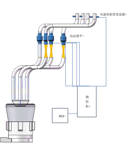
● Adopt dynamic-and-static adjustable devices (e.g. an electric adjustable device plus a static balancing fitting) for real-time correction under variable operating conditions;
● Perform multi-point balancing across multiple operating conditions to narrow the deviation over the full operating range and strive, as far as possible, for equal velocity throughout;
● For pulverized-coal concentration deviation, adopt a centrifugal dynamic separator to raise the pulverized-coal uniformity at the medium-speed mill outlet to ≥1.2; equal wind speeds can then basically represent uniform pulverized-coal concentration and uniform distribution of the powder mass flow.
6. Summary
For single-phase fluid pipelines, as long as the total resistance coefficients are made equal, the flow velocity can be kept consistent over the full operating range.
A coal-powder pipeline is a gas-solid two-phase flow; the resistance of each coal pipe varies with the airflow and pulverized-coal concentration in different ways. The adjustable orifice can only balance the wind speed at a single mill-output operating point; when the mill output changes, the resistance of each pipeline grows / decays by different amounts, so the flow velocities of the coal pipes will deviate again.



010-67184197、13311211762
dtly@datonglongyuan.com
Room E1-301, Oriental Plaza, No.1 East Chang' an Avenue, Dongcheng District, Beijing, China

Follow The Official WeChat Account